
The Linux kernel and its device drivers, operate in a region of memory separated from that of user programs. This separation is enforced by the microprocessor. When data and instructions must pass between the two, the communication is carefully controlled to protect the system from errant programs.
The mechanism used is the reading and writing from and to special filesystems hung on the normal disk file tree. These might be called "fake" or "pseudo-" filesystems, because they look like disk files, but are actually windows into the kernel. If you look at their size, you will typically find 0 bytes, but if you do a cat on them, you will get data back. That data is generated on the fly by the kernel and represents the absolutely up-to-the-microsecond kernel values. Some files let you 'echo' values into them, and those values immediately change what the kernel uses when it needs them.
The three pseudo-filesystems of interest here are:
/procThe proc filesystem allows you to read and sometimes write parameters used by the Linux kernel and its active drivers. As Linux is normally configured, most /proc values (like /proc/cpuinfo) can be read by ordinary users, but only the superuser (root user) may read and/or change certain parameters. The proc filesystem is described in the kernel documentation file Documentation/filesystems/proc.txt.
/sys
The sys filesystem exposes the state of the system's device drivers. Interacting with entries in /sys can allow the root user to bind/unbind drivers and start/stop debugging output. It is described in the kernel documentation file Documentation/filesystems/sysfs.txt. More information can be found in the Documentation/driver-model directory of the kernel source code tree.
/sys directory entries are created and removed as their corresponding drivers are automatically loaded and unloaded.
/dev
The dev filesystem accesses device drivers for data input/output. For example, the console (keyboard for input and display for output) is at /dev/console and we can send something to it by doing
echo "Message sent to the console." > /dev/console
This will send a message to the pseudo-terminal currently acting as the command-line console (When doing this in graphics mode, the real command-line console is hidden - it is the console from which the X-window system was started. Try doing this from a console obtained with <ctrl-alt-f1>. <ctrl-alt-f7> gets you back to the X-window system.)
/dev entries, like /sys entries are created and deleted automatically as drivers are loaded and unloaded
When programming Linux, there is a very important concept to remember:
"All devices are handled like ordinary disk files, they can be opened, read, and perhaps written to as dictated by their capabilities and associated permissions."
Each device driver is connected with at least one entry in the /dev directory, and it will handle a small number of functions that act on that entry. Some common functions are:
open()
An open command makes a temporary connection between the user program and the device handled by the driver.
read()
The driver will pass data from the device to the user program via a buffer specified in the read command.
write()
The driver will pass data from the user program to the device via a buffer specified in the write command.
select()
The select() command allows the monitoring of file descriptors so that one can know for sure that data is available for read() and allows the specification of a timeout limit.
ioctl()
The ioctl command is a catch-all that can handle transactions where read and write are not suitable. Typically, this means setting communication parameters or mode changes in the device. There is an upper limit of 16 KBytes for the amount of data that can be transferred via the ioctl command.
close()
This simply terminates the temporary connection made using open().
My computer has 6 USB ports that can connect to any of 3 USB 2.0 buses. I currently have built into my Linux kernel support for an EHCI hi-speed controller and an OHCI "full" speed controller.
When the DLP-2232PB-G device (see previous page for detailed references.) is plugged into a USB bus port on a computer running Linux, core USB software does the following:
cat on this "file" will return the USB descriptors of the device in unprocessed binary form. The /proc/bus/usb/devices file will then include information from the new device. Doing a cat on /proc/bus/usb/devices provides human-readable descriptor information and any drivers that are currently bound to the device./dev/bus/usb/003/012 is created. This device file can be used with the open, read, write, and ioctl system programming calls.The following device entries are created under /sys as well as various symbolic links connected to them:
/sys/bus/pci/devices/0000:00:03.1/usb3/3-3
For the control communication with the FT-2232C.
/sys/bus/pci/devices/0000:00:03.1/usb3/3-3/3-3:1.0
for communication with channel A of the FT-2232C.
/sys/bus/pci/devices/0000:00:03.1/usb3/3-3/3-3:2.0
for communication with channel B of the FT-2232C.
Finally, a search is made for any drivers (build-in or modules) that claim to be a match for the device. Linux has an ftdi_sio driver that will claim to drive anything with a vendor id of 0403 (FTDI) and a product id of 6001 or 6010 among many others. Therefore, the ftdi_sio driver will be bound to the DLP-2232M-G (product id of 6001) and to the DLP-2232PB-G (product id of 6010). (If ftdi_sio is a module, it will be automatically bound when loaded using the modprobe command.)
The binding process creates the following additional entries in the /sys and /dev directory trees:
/sys/bus/usb/drivers/ftdi_sio/bind
This pseudo-file is used to bind the ftdi_sio driver to the channel A interface of our FTDI device by doing:
cd /sys/bus/usb/devices/;
echo -n 3-3\:1.0 > ../drivers/ftdi_sio/bind
/sys/bus/usb/drivers/ftdi_sio/unbind
Similarly, the driver can be unbound by doing:
cd /sys/bus/usb/devices/;
echo -n 3-3\:1.0 > ../drivers/ftdi_sio/unbind
/dev/ttyUSB0 and /dev/ttyUSB1
Using these devices like a serial (tty, UART) device will communicate to channels A (ttyUSB0) and B (ttyUSB1) of the FT-2232C via the USB bus. Baudrate, line settings, etc., can be individually set using termios just as they are with any ordinary serial device.
/proc/tty/driver/usbserial is created. Doing a cat on it lists the devices that are associated with each /dev/ttyUSB* entry.The binding between driver and device also creates related links between the new ftdi_sio driver and the device entries in the /sys/ directory tree.
The interface lines in the device's /proc/bus/usb/devices file will now show that the ftdi_sio driver bound to them.
The entries under the /dev/bus/usb directory are actually all is required to gain full access to any USB device. The programming, however, can be quite tedious, and additional levels of code have been created to make it easier. Unfortunately, these additional levels nearly always reduce coding flexibility. They are:
ftdi_sio - A serial mode (tty) kernel-level driver that creates additional device entries that act like serial I/O (think modem, or serial port) devices.libusb - A application library of helper routines to allow easier utilization of /dev/bus/usb entries.libftdi - A application library of helper routines specific to the FTDI chips. libftdi uses the routines in libusb to interact with FTDI chip via the kernel USB system.It is clearly arguable how much capability should be put into the kernel, whether a specialized kernel driver is needed for a particular device, and whether general application libraries are justified. If application libraries are justified, how should they be organized?
Currently in Linux, the kernel USB code implements the USB 2.0 standard and related upkeep of /sys, /dev, and /proc. More specialized USB drivers should serve a common class of applications, such as interfacing traditional serial programming techniques with the USB system. The ftdi_sio driver serves a wide range of devices that use the FTDI chips as serial converters between USB and the legacy serial protocols.
The DLP-2232PB-G has both channels of its FT-2232C chip connected to a PIC16F877A microcontroller chip. Channel A is used for programming the PIC and channel B is used to send commands and get results. The FT-2232C EEPROM is set to make the FT-2232C power up with both channels in FIFO mode. This allows serial communication to pass through channel B of the FT-2232C into in the PIC16F877A. The default DLP firmware in the PIC16F877A takes the commands and provides responses via this serial connection:
application program <=> ftdi_sio <=> USB Bus <=> FT-2232C Channel B <=> PIC16F877A
This is illustrated in a simple application program that uses ftdi_sio to communicate with the DLP-2232PB-G protoboard.
This code necessarily uses asynchronous communication with special kernel messages called "signals" announcing the arrival of newly received data. Normally, serial communication is performed line-by-line with newline (0x10) characters marking the end of a line. The tty driver to which the ftdi_sio driver connects normally waits for the newline characters before passing the received message to the application program. If there are no newline characters, the application program gets hung on its read instruction.
Signals solve this problem, but signals need to know where to go.
From the normal documentation, it appears that asynchronous communication may be specified when opening the device by using the O_ASYNC parameter. This is not the case, however, since the tty driver does not yet know where to send the signals. Only after the fcntl command is used to explicitly set the owner of the newly opened file descriptor to the process id of the application program, can O_ASYNC be set. (See the simple application program for details.)
After requesting PIC16F877A to identify itself, the above program makes sure that the communication from application program to PIC16F877A correctly passes all possible 8-bits bytes. An incorrect setting of the termios parameters can lead to various control bytes being changed, dropped, or added.
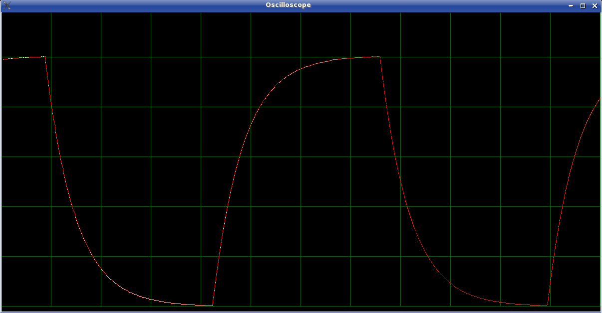
A program for using the computer and DLP-2232PB-G as a low-frequency oscilloscope is a rather straight-forward extension of the simple example given above. The only difficult part is the addition of X-windows code to display the resulting graph of voltage vs time. Its voltage range is 0.0 - 5.0 Volts with a resolution of 1 mV. Using the default DLP code in the 16F877A, the time resolution of this oscilloscope is 2 ms.
If you just want to monitor logic levels vs. time, you can display all 8 digital inputs of a 16F877A I/O port. You then have an 8-channel logic scope. Here is a program to do that which uses one of the pins as a trigger. Its time resolution is the same as the low-frequency oscilloscope since all 8 channels are communicated in a single byte from the 16F877A.
Modified 16F877A code that sends the readings in blocks can speed up this scope considerably. Here is the improved 8-channel logic scope output. The time resolution has improved to 4.0 microseconds/reading. The general-purpose oscilloscope using the unit's A/D converter ends up with 24 microseconds resolution when the modified code is used.
ftdi_sio, like most drivers, can handle an ioctl command. ioctl's are a way of submitting oddball commands to the device that cannot be handled using the open, read, and write commands. Typically, these have to do with communication mode changes.
The FT-2232C chip has a variety of communication modes and can have its EEPROM reprogrammed over the USB link. Accessing these capabilities involves sending control messages via the pathway that would normally be used only by the USB host controller. This is what the ioctl commands can do, but unfortunately, the ftdi_sio driver only allows a few ioctl commands related to changing the serial protocol. It does not allow general ioctl commands to be passed to the FTDI device. We could enhance the ftdi_sio driver, but we don't need to.
The solution is to disconnect and reconnect the ftdi_sio driver as needed from within the program. We must do this in order to read and write program code and data in the 16F877A of the DLP-2232PB-G unit. Whereas the command/response communication between the FTDI chip and the PIC chip is via channel B acting as a FIFO, the programing lines of the PIC chip are controlled by channel A in a special serial mode (MPSSE, see below) that must be set via an ioctl message. It is necessary to first contact the chip directly using the libftdi and libusb functions to set the communication mode of channel A of the FTDI chip.
When the DLP-2232PB-G is plugged in, the ftdi_sio driver is automatically connected with it. The programmer code first disconnects the ftdi_sio driver from channel A of the FT-2232C and then connects directly to the /dev/bus/usb/<device number> file. It uses libftdi functions to set its communications mode to MPSSE (Multi-Protocol Synchronous Serial Engine), a mode very nicely suited to programming the PIC chip.
Finally, a custom-written function, not available in either of those libraries, directly sends an ioctl call to the default device kernel driver handling /dev/bus/usb/<device number> entries (drivers/usb/core/devio.c) to tell it to again match up USB kernel drivers with the connected devices they can drive. Here is that function:
void reconnect_kernel_drivers(){
  int fd;
  int ret;
  int interface;
  unsigned int val1, val2;
  struct usb_ioctl {
    int ifno; /* interface 0..N ; negative numbers reserved */
    int ioctl_code; /* MUST encode size + direction of data so the
                     * macros in <asm/ioctl.h> give correct values */
    void *data; /* param buffer (in, or out) */
  };
  struct usb_ioctl command;

  val1 = 3 << 30 | 'U' << 8 | 18 | sizeof(command) << 16;
  val2 = 0 << 30 | 'U' << 8 | 23 | 0 << 16;
  printf("val1=%04X  val2=%04X \n", val1, val2);
  interface = 0;
  command.ifno = interface;
  command.ioctl_code = val2;
  command.data = NULL;

  fd = open("/dev/bus/usb/001/001", O_RDWR);
  printf("%04X\n",fd);

  ret = ioctl(fd, val1, &command);
  if (ret){
    err(1, NULL);
    printf("could not attach kernel driver to interface %d: %d\n", interface, ret);
  }
  close(fd);
}
Once the ftdi_sio driver has re-attached itself to our device, we will need to know which /dev/ttyUSB<port number> should be used. There is a routine called usb_device_nbr() in the load_16f877a.c code that uses the /sys directory to match the correct port number with the identification strings for the particular device, including a description string and a serial number string.
After a wait of about 50 mS, the connection to /dev/ttyUSB<port number> can be made, MPSSE programming initiated, and PIC16F877A program code read and written.
The programmer code works, but is not as efficient as it should be. For some reason, I found it necessary to leave and return to programming mode after each write, and to reset the program counter to the appropriate value for the next write. This leads to increasingly inefficient programming as the address of the code increases. Fortunately, the speed of programming is sufficiently high that complete programming is still possible in about 12 seconds. This inefficiency should be resolved before too long.
This same technique for mixing libftdi, libusb, ftdi_sio driver, and default driver code also allows seamless programming of the EEPROM connected to the FT-2232C chip.
When using the DLP-2232PB-G or when changing its embedded code, the actual commands and data pass through at least three processors and at least 3 communication protocols with associated buffers and clock rates:
The PIC microcontroller has a 20 MHz clock crystal and can execute most instructions in 4 clock cycles (200 nS). Assembly language programming of this microcontroller is by far the best way to control and read voltage levels on a sub-millisecond level.
Its D/A converters clock at a slower rate by a factor that depends on the crystal frequency. For 20 MHz controller crystal, the A/D clock divider can be set to 1/32 or 1/64. A minimum of 12 A/D clock cycles are required for a conversion, so with a divider of 32, a conversion requires 19.2 microseconds. Reporting the 10-bit result requires 2 bytes of communication.
The default DLP microcode in the PIC microcontroller looks for commands to arrive on its Port D pins. The command to read a A/D takes 4 bytes. Thus, 6 bytes of communication are used for each reading. Receiving a byte takes a minimum of 26 uS and sending one takes a minimum of 77 uS. The command processing adds more time so that the total time required for a single D/A reading is at least 600 uS. In reality, the turnaround time seems to be about 2000 uS.
With modified DLP microcode that does measurements in blocks of up to 65536 readings, I have obtained digital state readings at a rate of 4 microseconds per 8-channel reading. Similar changes to the A/D reading code acquires 10-bit samples at a rate of 24 microseconds/reading. These speeds are adequate for use as a simple oscilloscope.
The FT2232C chip has various modes of communication, two of which are used in communicating with the 16F877A. The MPSSE (Multi-Protocol Synchronous Serial Engine) capability of its A channel is used to alter the embedded code in the 16F877A via a serial connection, and its B channel is used in FIFO mode to exchange commands and data with Port D of the 16F877A via a parallel connection.
The EEPROM connected to the FT2232C in the DLP-2232PB-G unit is preset to make the FT2232C power up with both of its channels in the FIFO mode. The FIFO mode transmits and receives 8 bits in parallel using 5 additional lines which control the timing of the transfer. A minimum of 335 nS is required to send a byte to the 16F877A in the FIFO and 225 nS to receive one. This is much faster than the 16F877 processes them so these times should not matter when exchanging data with it via the B channel of the FT2232C.
The A channel must be set to MPSSE mode (FTDI Application Note AN2232C-01) using a libftdi function ftdi_set_bitmode() as demonstrated in the programmer code. The MSSE receives simple commands along with the data to be sent and clocks out the data bits as directed.
The MPSSE clock rate is 6 MHz divided by 1 plus a two-byte divisor. It can be set from 6 MHz to 91.553 Hz with the divisor ranging from 1 to 0xFFFF. At the 6 MHz rate, the data is clocked out at 5.6 Mbits/second. With Vdd = 5 V as it is in the DLP-2232PB-G, this satisfies the timing limits of the 16F877A Programming modes, except when memory erasing and writing are involved. In those cases delays of 1 or 4 mS are needed after the command. Unfortunately, there is no suitable MPSSE delay command and we must program that delay keeping in mind that there are buffers between our application program and the MPSSE. (The Wait on Hi/Lo MPSSE command needs a signal from the 16F877A when the erase/writing command completes, but no such signal is available.)
The "baudrate" setting only affects the UART mode of the FT2232C and we are not using that mode on either channel in the DLP-2232PB-G.
The USB side of the FT2232C chip runs at "full speed" which is at most 12 Mbits/second. Each channel has a 128-byte transmit buffer and a 384-byte receive buffer. The FT2232C USB descriptors state that the maximum packet size is 64 bytes in bulk transfer mode. 12 Mbit/S with this buffering seems adequate to supply the 16F877A without delay even at the 6 MHz MPSSE clock setting. It is also sufficient to exchange data via the B channel FIFO connection as fast the 16F877A can handle. The speed in FIFO mode is controlled by handshaking with the 16F877A.
The Linux USB subsystem uses the buffers of the application program except when doing tty-style serial communication as is done by the ftdi_sio driver. The Linux kernel tty driver seems to use 16-kByte buffers that are committed when 2/3 full. The buffering has two important effects: 1) the application program has no way of knowing when the data actually reaches its destination unless a reply is returned, and 2) any time delay inserted between commands at the application program will be lost. Even the small buffers in the FT2232C chip will have these effects.
While making the overall system more efficient, the buffering complicates the application program and can even cause it to finish well before the last of the data have reached the 16F877A.
The application program has only two ways to control the timing of measurements:
Linux is a multi-tasking system and continually switches between tasks with a complicated priority system. This switching can disrupt the timing of data acquisition on a 10 mS scale. The original oscilloscope program (if run by the root user) will temporarily raise its priority to the maximum possible when executing its getData() function. This is done using a library function nice() (see man 3 nice), and works very well on a 1 mS scale.
The fancier oscilloscope program that uses bursts of readings does not need nice() because its measurement timing is dependent only on the loop timings of the 16F877A microcode. The buffering in the computer and the speeds of the FT2232C and USB line are sufficient to prevent any measurement delays.
The buffering is not a problem when you expect a response back before you must delay, but if you must delay in the midst of output without responses, you must create your own marker that doesn't disturb your output stream. Loopback, id query, or illegal instructions can be used for that purpose.
For example in MPSSE mode when programming the 16F877A, you need a 4 mS delay after certain commands. Sending an illegal instruction with bit 7 set, like 0xFF (or contrary to that specification, any command from 0x00 through 0x0F) will cause the MPSSE command processor to send back an 0xFA followed by your illegal command byte. This assures you that the buffer contents up to that point have been passed along to the 16F877A. Waiting 4 mS from that time and then sending the next instruction guarantees that there will be at least a 4 mS delay in spite of the buffering.
This marking process is quite costly in time since it appears that each mark costs 15 mS on my system since low-volume, round-trip communication is costly. One way travel seems to be faster than 4 uS/byte. The USB protocol is not very efficient when sending single bytes back and forth. A better solution is to know the system timing well enough that a command might be sent that sets an unused pin, but doesn't reply back. For example, a 4 mS delay can be achieved on my system by sending 180 set_data_bits_high_byte() commands.
Last updated: September 13, 2007
![]()