
The Linux kernel will usually be installed with its usb and usbserial drivers available as automatically activated modules. Alternatively, they may be built into the kernel if desired. The library libusb will also usually be installed.
Also available in the Linux kernel source is a serial driver for devices that use the FTDI USB interface chips. This driver, called ftdi_sio, might not be included in your Linux kernel binary. If not, recompile the kernel from the Linux source code and select "Device drivers->USB support->USB Serial Converter Support->USB FTDI Single-Port Serial Driver" (CONFIG_USB_SERIAL_FTDI_SIO). The driver blurb says "single-port", but in fact, it works with the dual-port FT2232C chip.
When an FTDI-based USB device is plugged in, the system binds the ftdi_sio driver to it. The driver then creates /dev/ttyUSBx ports (major device number 188) which an application can use for input and output just like a standard serial I/O port. The USB nature of the communication is hidden from the application as data is exchanged between the device and the application program.
All USB devices, whether serial or not, automatically acquire a device entry under /dev/bus/usb/00*/*. These entries have typically have major number 189 and a minor number corresponding to the next available USB device number.
The current version of ftdi_sio, however, only allows access to the chip's UART modes. It does not allow bit-banging or access to the associated user EEPROM. A library called libftdi bypasses the ftdi_sio driver and directly accesses the Linux USB core drivers via another library called libusb. Using libftdi, one can do bit-banging and read/write/erase the user EEPROM attached to the FTDI USB chips.
libftdi, however, needs to be downloaded, compiled, and installed as described below. I have modified it to better handle the FT2232C chip. You may want to try my versions of ftdi.h and ftdi.c, but keep in mind they are still a work in progress.
Convenient development assemblies using the FTDI chips are produced by DLP Design. Their DLP-2232M-G USB Adapter is a 40-pin DIP board with the FTDI chip, a clock crystal, 256-byte EEPROM, some power control circuitry, and a USB connector. Their DLP-2232PB-G USB Adapter adds a Microchip 16F877A microcontroller to this and mounts it on a small 50-pin printed-circuit board. The 16F877A is pre-coded to allow A/D conversion, bit I/O, and the sensing of DS18S20 "1-wire" chip thermometers.
I have recently added to the default code in the 16F877A to allow it to process additional DS18S20/DS18B20 commands involving their ROM-coded identification strings, including the Search ROM command that allows the enumeration of all sensors attached to a given 16F877A input pin. The modified DLP code also has commands to remotely control my CD-500 Mavica camera. The C program that uses the new capabilities is composed of five include files:
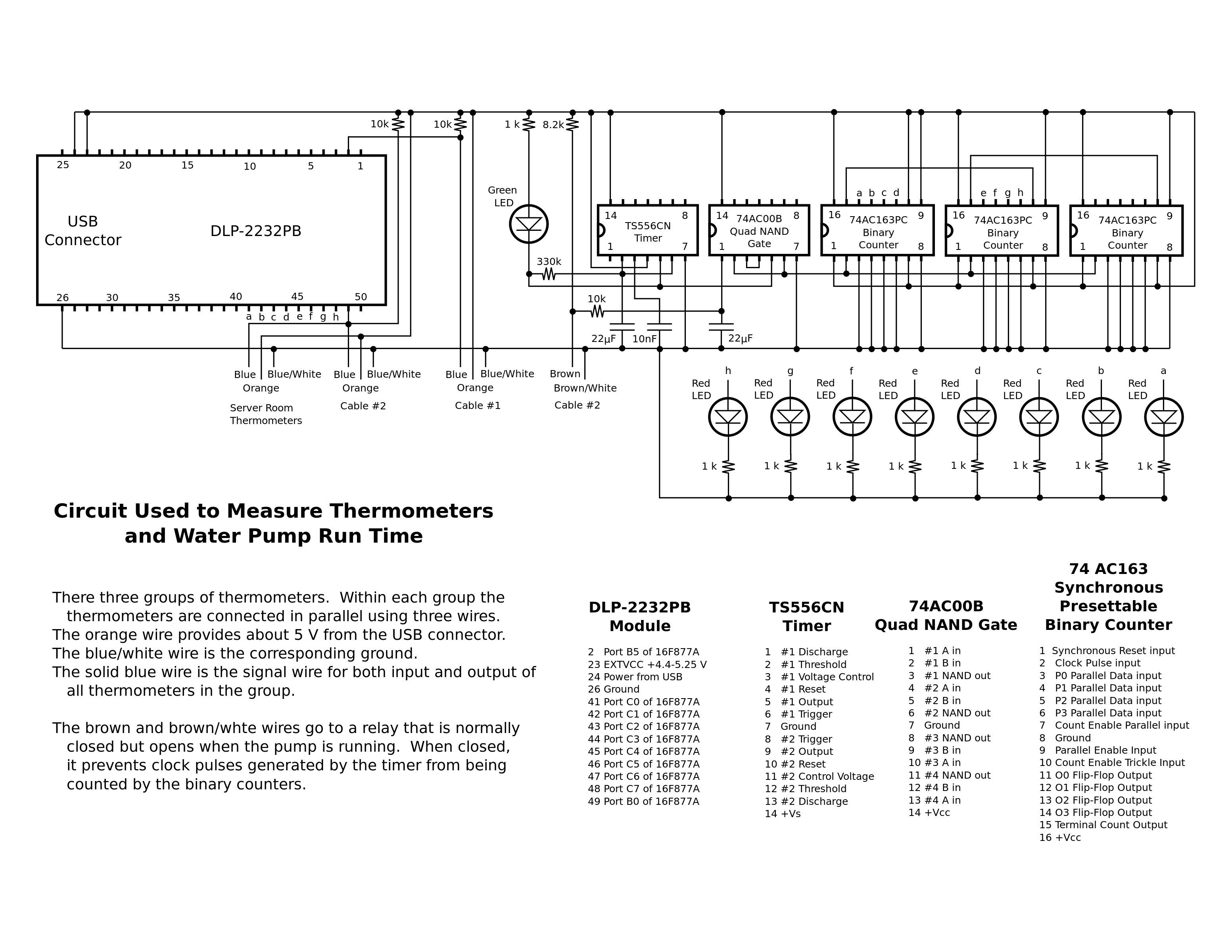
These are demonstrated by scope.c, temperature_monitor.c, and mavica.c. I run thermometer_monitor.c as a cron job with its output redirected to a temperature log file. The circuit arrangement for checking temperatures and pump run time is here.
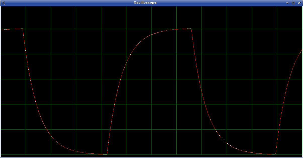
The scope.c program produces displays of both analog voltage changes and simultaneous monitoring of 8 digital signals. The original code in the 16F877a only made one reading per command. To make a useful oscilloscope, my modified code makes bursts of readings for each command. This was useful for analyzing the communication between my Mavica CD-500 camera and its remote and another DLP-2232PB-G programmed to behave like the remote.
I am currently monitoring 35 temperature sensors with the temperature_monitor.c program. It determines what thermometers are present and gets their readings in 2 seconds. I run it every 15 minutes as a cron job.
The assembly code is compiled and linked using the gputils tools, and loaded into the DLP-2232PB-G using this C program which uses the in-circuit programming capability of the DLP-2232PB-G.
When studying this oscilloscope demo program, pay close attention to how the serial I/O is set up. The DLP-2232PB-G has responses of predictable length, but no termination character. It is therefore crucial to open the serial communication in asynchronous mode with signals used to flush the responses from the USB subsystem to the application read statement. The system call select() is used to allow a timeout of the read() calls.
The original "oscilloscope" program without bursts of readings had irregularities caused by the multi-tasking of Linux. These were minimized by running as root and adjusting priority by doing nice --adjustment=-20 ./scope. Alternatively, the C-library routine nice() can be placed around the time-sensitive data collection code.
The version that uses bursts does not have this problem because its measurement timing is determined by the instruction loop in the PIC16F877A chip. Also, there is much less 2-way traffic on the USB bus and the system buffering is able to hide the effects of system multi-tasking. A further refinement is to use separate execution threads for parts of the program that might cause delays, like the scope display and thermometer reading routines.
Don L. Powie of DLP Design has written the following useful articles related to the use of the FTDI USB Inteface chips:
This describes directly connecting a FT2232C chip to an D/A chip, a A/D chip, and a buffer to drive LEDs and relays.
The DLP-2232PB-G Data Sheet has the circuit layout for how it combines the FT2232C to the PIC16F877 as well as how to utilize the demonstration embedded code inside the PIC16F877A. That code allows one to read analog voltages, read/set digital voltages, read single-wire thermometers, and read/write the user EEPROM (not to be confused with the EEPROM connected to the FT2232C chip that we must use libftdi to access).
The FTDI documentation of the FT2232C chip only describes its hardware. Its firmware, unfortunately, is poorly documented. They expect users to use Microsoft drivers and their programs that only run on Microsoft systems. Here is my attempt to collect documentation of the FTDI chip commands.
The PIC16F877A microcontroller chip is fully documented, but be sure also to look at their erratum.
Maxim's documentation of their DS18S20 single-wire chip thermometer is also complete.
The USB 2.0 Standard document is crucial to understanding the details of USB interfacing. The protocols, descriptors, and many other important details of the USB 2.0 standard are described in this 650-page document which can be downloaded from USB Implementers Forum, Inc.. The first 5 chapters and Chapter 9 are particularly relevant to USB programming.
The following procedure allowed me to use the ftdi examples listed below:
Downloaded libftdi-0.8.tar.gz from Intra2net, placing it in an empty directory.
Unpacked to that directory using the following commands:
$tar xzf libftdi-0.8.tar.gz
$cd libftdi-0.8
$./configure
$make
$su
<root user password >
#make install
#cd /usr/lib
#cp ../local/lib/libftdi.so.0.8.0 .
#ln -s libftdi.so.0.8.0 libftdi.so.0
#ln -s libftdi.so.0 libftdi.so
#ldconfig
Adjust the version numbers as needed. As of June, 2012, 0.8.0 needed to be replaced with 1.20.0 and so.0 needed to be replaced by so.1 to match libftdi-0.20.tar.gz.
If you get an error message like "configure: error: *** libusb-config not found. You need a working libusb installation.", you need to install libusb-dev by doing apt-get install libusb-dev as root.
(Alternatively, the Makefile could be edited to use /usr as the prefix instead of /usr/local. Then the last 5 lines would be unnecessary.)
This example, a modified version of one obtained under GPL license from Intra2net, uses bit banging to turn on all bits on FT2232C channel A. It does the following:
This examples uses the ftdi functions as follows (errors reported using ftdi_error):
To run this bitbang example, first inspect its code to see if it has the correct vendor_id and product_id for your device. (lsusb -v reveals these.) Edit accordingly. I needed to change product_id from 0x6001 to 0x6010.
The example is then complied and tested using:
$cc -Wall -lftdi libftdi_example_bitbang2232.c -o bitbang2232
$./bitbang2232
It should print out the following:
ftdi open succeeded: 0
enabling bitbang mode
ftdi open succeeded: 0
enabling bitbang mode
turning everything on
turning everything off
fe fd fb f7 ef df bf 7f
fe fd fb f7 ef df bf 7f
disabling bitbang mode
If you get an error messages stating unable to open ftdi device: -3 - device not found, you probably still don't have the correct vendor and product numbers.
If your device can not be found using lsusb -v, then check to see if it is plugged in and the pins 17-20 on the DLP-2232M-G are connected correctly for selecting power.
If you get a message ftdi open succeeded: -5 followed later by some write failed for 0x0, error -22 - usb bulk write failed messages, other drivers are claiming control of the device. In my system, the usbi_sio driver was claiming the board until I changed the product id.
Because I had built the ftdi_sio driver into my Linux kernel, I had to do the following (as root) to "unbind" that driver:
 cd /sys/bus/usb/drivers/ftdi_sio
 echo -n 3-3:1.0 > unbind
 echo -n 3-3:1.1 > unbind
Here, the 3-3:1.0 and 3-3:1.1 numbers are the names of links found in that same directory that shows which devices are bound to the ftdi_sio driver.
If your ftdi_sio driver is a module, you simply do rmmod ftdi_sio to unbind it.
This example has been modified from one, also under GPL license, that is available from Intra2net. When using this version, be sure to also use the modified libftdi code since the ftdi eeprom routines needed modification to work with the FT2232C chip. This program allows you to read, erase, and flash the EEPROM in the FT2232C chip. An optional configuration file can be used with it. To compile it, I needed to also download libconfuse-2.5-1.src.rpm and compile libconfuse first since it was not already installed on my system. The compilation and installation was done as follows:
First, download libconfuse-2.5-1.src.rpm from Mandriva or another Linux distribution
Then do the following:
#rpm -Uvh libconfuse-2.5-1.src.rpm
#cd /usr/src/rpm/SOURCES/libconfuse-2.5
#./configure
#make
#make install
Download ftdi_eeprom-0.2.tar.gz from Intra2net
#tar xzf ftdi_eeprom-0.2.tar.gz
#cd ftdi_eeprom-0.2
#./configure
#make
#make install
#ftdi_eeprom --read-eeprom example.conf
This should print out the following:
FTDI eeprom generator v0.2
(c) Intra2net AG <opensource@intra2net.com>
FTDI init: 0
FTDI read eeprom: 0
FTDI close: 0
and your eeprom code should be in the file named in example.conf. Its 256 bytes can be examined using the hexedit program:
00000000   01 01 03 04  10 60 00 05  80 2D 08 00  00 02 96 0A  .....`...-......
00000010   A0 12 B2 12  56 00 00 00  00 00 00 00  00 00 00 00  ....V...........
00000020   00 00 00 00  00 00 00 00  00 00 00 00  00 00 00 00  ................
00000030   00 00 00 00  00 00 00 00  00 00 00 00  00 00 00 00  ................
00000040   00 00 00 00  00 00 00 00  00 00 00 00  00 00 00 00  ................
00000050   00 00 00 00  00 00 00 00  00 00 00 00  00 00 00 00  ................
00000060   00 00 00 00  00 00 00 00  00 00 00 00  00 00 00 00  ................
00000070   00 00 00 00  00 00 00 00  00 00 00 00  00 00 00 00  ................
00000080   00 00 00 00  00 00 00 00  00 00 00 00  00 00 00 00  ................
00000090   00 00 00 00  00 00 16 03  44 00 4C 00  50 00 20 00  ........D.L.P. .
000000A0   44 00 65 00  73 00 69 00  67 00 6E 00  16 03 44 00  D.e.s.i.g.n...D.
000000B0   4C 00 50 00  2D 00 32 00  32 00 33 00  32 00 50 00  L.P.-.2.2.3.2.P.
000000C0   42 00 12 03  44 00 50 00  34 00 30 00  4D 00 39 00  B...D.P.4.0.M.9.
000000D0   31 00 44 00  02 03 00 00  00 00 00 00  00 00 00 00  1.D.............
000000E0   00 00 00 00  00 00 00 00  00 00 00 00  00 00 00 00  ................
000000F0   00 00 00 00  00 00 00 00  00 00 00 00  00 00 75 B0  ..............u.
Two-byte data (manufacturer id, product id, USB version, and Unicode characters) are 16-bit words which are stored with the low byte lower in memory. A descriptor string, however, is sent out from memory going from low address to high address and these 16-bit words must be reversed when sent out in order for the computer to receive them in low-order byte first.
These EEPROM bytes signify the following:
The string data that follows is placed starting at address 0x14 in earlier chips that had only a 128-byte EEPROM, but must start at 0x96 in the FT2232C chip which has a 256-byte EEPROM.
The FTDI-2232C sets its language Id to 0x0409 (US English) in ROM. It cannot be changed.
Of course, certain settings must be modified to match your system.
When the EEPROM settings are changed, they are not put into effect until the unit has been reset either by using the RSTIN (pin 27 of the DLP2232M-G, pin 4 of the FTDI2232C) or by unplugging and replugging the device.
This EEPROM program example uses the following libftdi functions:
It is a good idea to make sure that the bitbang2232 example described above works correctly to be sure that the library and device are talking to each other, before changing the EEPROM.
The Linux USB Project has a great deal of useful information for programmers of USB for Linux.
Sometimes when testing the DLP2232M-G, you may want to put it in USB suspend mode. If your linux kernel has CONFIG_USB_SUSPEND compiled in, you can suspend a device by doing:
$su
<give root password>
#cd /sys/bus/usb/devices/
#ls
1-0:1.0@  2-0:1.0@  3-0:1.0@  3-3@  3-3:1.0@  3-3:1.1@  usb1@  usb2@  usb3@
#ls 3-3/
3-3:1.0/             bDeviceClass     bMaxPacketSize0     bus@           ep_00/        maxchild  speed
3-3:1.1/             bDeviceProtocol  bMaxPower           configuration  idProduct     power/    uevent
bcdDevice            bDeviceSubClass  bNumConfigurations  devnum         idVendor      product   usb_device:usbdev3.18@
bConfigurationValue  bmAttributes     bNumInterfaces      driver@        manufacturer  serial    version
#ls 3-3/power/
state wakeup
#cat 3-3/power/*
0
wakeup
#echo -n 2 > 3-3/power/state
#ls
state wakeup
#cat 3-3/power/*
2
enabled
The cat 3-3/power/wakeup will return enabled if the DLP2232M-G has "wakeup on suspend" enabled in its EEPROM. You can take it out of suspend by echoing a 0 into 3-3/power/state. Temporarily forcing the DLP2232M-G pins <SI/WUA> or <SI/WUB> or UART ring indicators to a low voltage state will also take it out of suspend.
Of course as before, 3-3 was my device code, yours will likely be different. Also, if you had made the power directory your working directory, you would have found a somewhat confusing result since that directory will be removed and recreated on a different filesystem inode number when the power condition is changed. Similarly, if the device is disconnected and reconnected, the 3-3 directory will be recreated on a different inode.
If "wakeup on suspend" is not set in the DLP2232M-G EEPROM, cat 3-3/power/wakeup will simply return a blank line.
On other occasions, I might want the driver to unbind. I can cause that to happen in three ways:
Unbind the driver by rmmod on its module, or if it is built into the kernel, by doing the following as root:
$su
<give root password>
#cd /sys/bus/usb/drivers/usb
#ls
3-3@  bind  unbind  usb1@  usb2@  usb3@
#echo -n 3-3 > unbind
#ls
bind  unbind  usb1@  usb2@  usb3@
The device link for the DLP2232M-G, 3-3 in this example, disappears when unbound. Be sure you have identified the right device link. Doing cat 3-3/id* will show the product and manufacturer id numbers for device 3-3.
Since this removes the /sys/bus/usb/ entries for the device. You cannot selectively rebind it using /sys; you must unplug and replug the device. It might be possible to force the system to look for devices again, but I am not sure how.
Compiling the Linux kernel with CONFIG_USB_DEBUG set will cause USB activity to be logged to /var/log/kernel/info. This can be very helpful.
Even more detailed logging from inside of the drivers is available by echoing a 'Y' into the debug "file" in /sys for that driver. For example with the ftdi_sio driver, one does (as root):
#echo 'Y' > /sys/module/ftdi_sio/parameters/debug
I edited /etc/syslog.conf so that the kernel debug logging would be sent to /var/log/kernel/debug. This prevents the normal log files from being filled with the massive debug information.
Other debug logging is turned on by doing:
echo -n 'Y' > /sys/module/usbcore/parameters/usbfs_snoop
Both of these, of course, can be turned off again by echoing 'N' into the pseudofile.
libusb is the core library of routines that handle the USB 2.0 Protocols in Linux. Other specialized drivers and user programs work through it. libftdi routines are simply functions specialized for the FTDI chips that call libusb routines.
Java is a great language for writing GUI code. These notes describe how to get a Java program to access the ftdi and usb-sio library code.
Last updated: June 27, 2012
![]()